Arduino PCB Project
An Arduino Uno was reverse engineered and a small PCB with all necessary components was designed using Mentor PADS software and made ready to be sent in for fabrication. All parts used in the PCB design were imported from Digikey's PartQuest database.
First the electrical schematic was designed in PADS schematic design software. Most elements needed to have their design customized to improve readability of the schematic. Sparkfun's Redboard design was used as a template for the schematic designs. Once all components were placed on the schematic all connections were laid out and verified for connectivity.
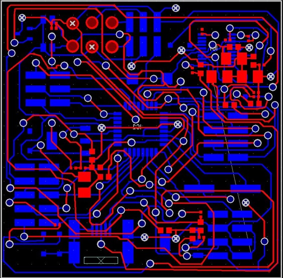
Once the schematic was completed the design was imported into PADS PCB design software. Each element was laid out and the onto a board not to exceed 2"x2" and all components were routed by hand. Both sides of the PCB were used for routing and connected using vias. The finalized design was checked using PADS native error checking software, and the gerber files were created. At the end of the project the PCB was ready to be submitted for fabrication.